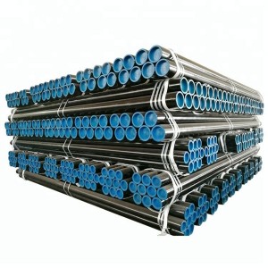
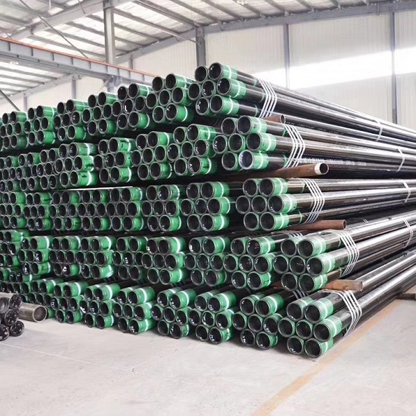
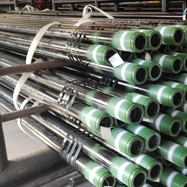
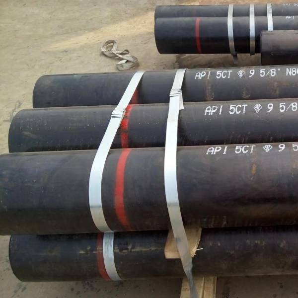
Specification for Casing and Tubing API SPECIFICATION 5CT NINTH EDITION-2012


| Standard: API 5CT | Alloy Or Not: Not |
| Grade Group: J55,K55,N80,L80,P110, etc | Application: Oiled&Casing Pipe |
| Thickness: 1 - 100 mm | Surface Treatment: As customer's requirement |
| Outer Diameter(Round): 10 - 1000 mm | Technique:Hot Rolled |
| Length: R1,R2,R3 | Heat treatment: Quenching &Normalizing |
| Section Shape: Round | Special Pipe: Short joint |
| Place of Origin: China | Usage: Oiled and Gas |
| Certification: ISO9001:2008 | Test: NDT |
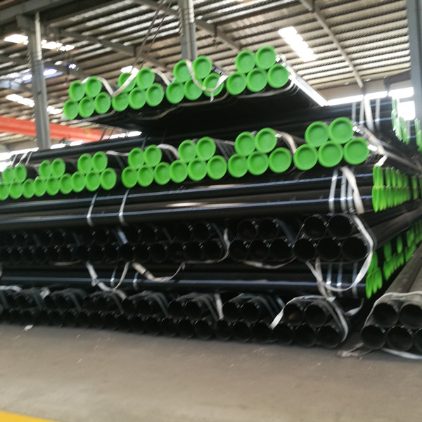
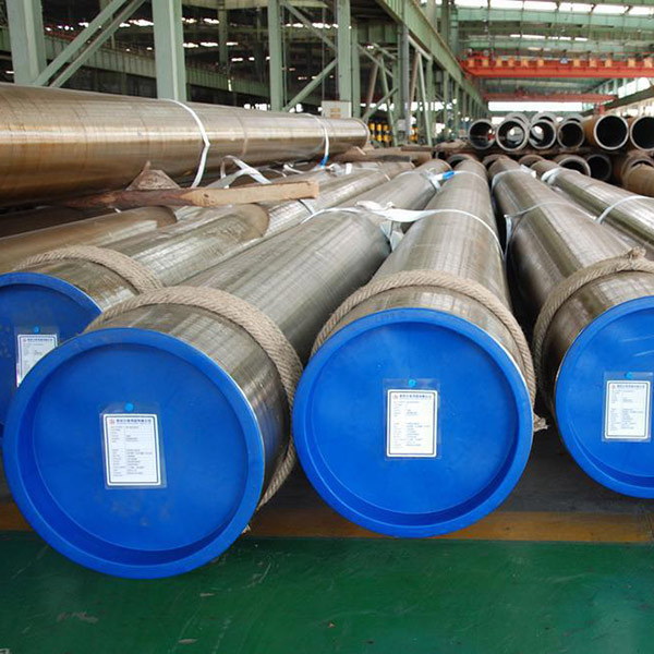
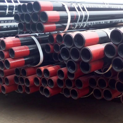
Pipe in Api5ct is mainly used for drilling of oil and gas wells and transportation of oil and gas. Oil casing is mainly used to support the borehole wall during and after the completion of the well to ensure the normal operation of the well and the completion of the well.
Grade :J55,K55,N80,L80,P110, etc
| Grade | Type | C | Mn | Mo | Cr | Ni | Cu | P | s | Si | ||||
| min | max | min | max | min | max | min | max | max | max | max | max | max | ||
| 1 | 2 | 3 | 4 | 5 | 6 | 7 | 8 | 9 | 10 | 11 | 12 | 13 | 14 | 15 |
| H40 | — | — | — | — | — | — | — | — | — | — | — | — | 0.03 | — |
| J55 | — | — | — | — | — | — | — | — | — | — | — | — | 0.03 | — |
| K55 | — | — | — | — | — | — | — | — | — | — | — | — | 0.03 | — |
| N80 | 1 | — | — | — | — | — | — | — | — | — | — | 0.03 | 0.03 | — |
| N80 | Q | — | — | — | — | — | — | — | — | — | — | 0.03 | 0.03 | — |
| R95 | — | — | 0.45 c | — | 1.9 | — | — | — | — | — | — | 0.03 | 0.03 | 0.45 |
| L80 | 1 | — | 0.43 a | — | 1.9 | — | — | — | — | 0.25 | 0.35 | 0.03 | 0.03 | 0.45 |
| L80 | 9Cr | — | 0.15 | 0.3 | 0.6 | 0 90 | 1.1 | 8 | 10 | 0.5 | 0.25 | 0.02 | 0.03 | 1 |
| L80 | 13Cr | 0.15 | 0.22 | 0.25 | 1 | — | — | 12 | 14 | 0.5 | 0.25 | 0.02 | 0.03 | 1 |
| C90 | 1 | — | 0.35 | — | 1.2 | 0.25 b | 0.85 | — | 1.5 | 0.99 | — | 0.02 | 0.03 | — |
| T95 | 1 | — | 0.35 | — | 1.2 | 0.25 b | 0.85 | 0 40 | 1.5 | 0.99 | — | 0 020 | 0.01 | — |
| C110 | — | — | 0.35 | — | 1.2 | 0.25 | 1 | 0.4 | 1.5 | 0.99 | — | 0.02 | 0.005 | — |
| P1I0 | e | — | 一 | — | — | — | — | — | — | — | — | 0.030 e | 0.030 e | — |
| QI25 | 1 | — | 0.35 | 1.35 | — | 0.85 | — | 1.5 | 0.99 | — | 0.02 | 0.01 | — | |
| NOTE Elements shown shall be reported in product analysis | ||||||||||||||
| a The carbon content for L80 may be increased up to 0.50% maximum if the product is oil-quenched or polymer-quenched. | ||||||||||||||
| b The molybdenum content for Grade C90 Type 1 has no minimum tolerance if the wall thickness is less than 17.78 mm. | ||||||||||||||
| c The carbon contect for R95 may be increased up to 0.55% maximum if the product is oil-quenched. | ||||||||||||||
| d The molybdenum content for T95 Type 1 may be decreased to 0.15% minimum if the wall thickness is less than 17.78 mm. | ||||||||||||||
| e For EW Grade P110, the phosphorus content shall be 0.020% maximum and the sulfur content 0.010% maximum. | ||||||||||||||
|
Grade |
Type |
Total Elongation Under Load |
Yield Strength |
Tensile Strength |
Hardness a,c |
Specified Wall Thickness |
Allowable Hardness Variation b |
||
|
|
|
|
|
|
|
|
|
||
|
|
|
|
min |
max |
|
HRC |
HBW |
mm |
HRC |
|
H40 |
— |
0.5 |
276 |
552 |
414 |
— |
— |
— |
— |
|
J55 |
— |
0.5 |
379 |
552 |
517 |
— |
— |
— |
— |
|
K55 |
— |
0.5 |
379 |
552 |
655 |
— |
— |
— |
— |
|
N80 |
1 |
0.5 |
552 |
758 |
689 |
— |
— |
— |
— |
|
N80 |
Q |
0.5 |
552 |
758 |
689 |
— |
— |
— |
— |
|
R95 |
— |
0.5 |
655 |
758 |
724 |
— |
— |
— |
— |
|
L80 |
1 |
0.5 |
552 |
655 |
655 |
23.0 |
241.0 |
— |
— |
|
L80 |
9Cr |
0.5 |
552 |
655 |
655 |
23.0 |
241.0 |
— |
— |
|
L80 |
l3Cr |
0.5 |
552 |
655 |
655 |
23.0 |
241.0 |
— |
— |
|
C90 |
1 |
0.5 |
621 |
724 |
689 |
25.4 |
255.0 |
≤12.70 |
3.0 |
|
12.71 to 19.04 |
4.0 |
||||||||
|
19.05 to 25.39 |
5.0 |
||||||||
|
≥25.4 |
6.0 |
||||||||
|
T95 |
1 |
0.5 |
655 |
758 |
724 |
25.4 |
255 |
≤12.70 |
3.0 |
|
12.71 to 19.04 |
4.0 |
||||||||
|
19.05 to 25.39 |
5.0 |
||||||||
|
≥25.4 |
6.0 |
||||||||
|
C110 |
— |
0.7 |
758 |
828 |
793 |
30.0 |
286.0 |
≤12.70 |
3.0 |
|
12.71 to 19.04 |
4.0 |
||||||||
|
19.05 to 25.39 |
5.0 |
||||||||
|
≥25.4 |
6.0 |
||||||||
|
P110 |
— |
0.6 |
758 |
965 |
862 |
— |
— |
— |
— |
|
Q125 |
1 |
0.65 |
862 |
1034 |
931 |
b |
— |
≤12.70 |
3.0 |
|
12.71 to 19.04 |
4.0 |
||||||||
|
19.05 |
5.0 |
||||||||
| a In case of dispute, laboratory Rockwell C hardness testing shall be used as the referee method. | |||||||||
| b No hardness limits are specified, but the maximum variation is restricted as a manufacturing control in accordance with 7.8 and 7.9. | |||||||||
| c For through-wall hardness tests of Grades L80 (all types), C90, T95 and C110, the requirements stated in HRC scale are for maximum mean hardness number. | |||||||||
In addition to ensuring chemical composition and mechanical properties, hydrostatic tests are performed one by one, and flaring and flattening tests are performed. . In addition, there are certain requirements for the microstructure, grain size, and decarburization layer of the finished steel pipe.
Tensile Test:
1. For the steel material of the products, manufacturer should perform tensile test. For the elecrtrice welded pipe, depondeds on manufacturer's choice, tensile test can be performed on the steel plate that used to make pipe or perfomred on steel pipe directly. An test performed on a product can also be used as a product test.
2. The test tubes shall be randomly selected. When multiple tests are required, the sampling method shall ensure that the samples taken can represent the beginning and end of the heat treatment cycle (if applicable) and both ends of the tube. When multiple tests are required, the pattern shall be taken from different tubes except that the thickened tube sample may be taken from both ends of a tube.
3. The seamless pipe sample can be taken at any position on the circumference of the pipe; the welded pipe sample should be taken at about 90 ° to the weld seam, or at the option of the manufacturer. Samples are taken at about a quarter of the strip width.
4. No matter before and after the experiment, if the sample preparation is found to be defective or there is a lack of materials irrelevant to the purpose of the experiment, the sample may be scrapped and replaced with another sample made from the same tube.
5. If a tensile test representing a batch of products does not meet the requirements, the manufacturer may take another 3 tubes from the same batch of tubes for re-inspection.
If all the retests of the samples meet the requirements, the batch of tubes is qualified except the unqualified tube that was originally sampled.
If more than one sample is initially sampled or one or more samples for retesting do not meet the specified requirements, the manufacturer may inspect the batch of tubes one by one.
The rejected batch of products can be reheated and reprocessed as a new batch.
Flattening Test:
1. The test specimen shall be a test ring or end cut of not less than 63.5mm (2-1 / 2in).
2. Specimens may be cut before heat treatment, but subject to the same heat treatment as the pipe represented. If a batch test is used, measures shall be taken to identify the relationship between the sample and the sampling tube. Each furnace in each batch should be crushed.
3. The specimen shall be flattened between two parallel plates. In each set of flattening test specimens, one weld was flattened at 90 ° and the other flattened at 0 °. The specimen shall be flattened until the tube walls are in contact. Before the distance between the parallel plates is less than the specified value, no cracks or breaks should appear in any part of the pattern. During the entire flattening process, there should be no poor structure, welds not fused, delamination, metal overburning, or metal extrusion.
4. No matter before and after the experiment, if the sample preparation is found to be defective or there is a lack of materials irrelevant to the purpose of the experiment, the sample may be scrapped and replaced with another sample made from the same tube.
5. If any sample representing a tube does not meet the specified requirements, the manufacturer may take a sample from the same end of the tube for supplementary testing until the requirements are met. However, the length of the finished pipe after sampling must not be less than 80% of the original length. If any sample of a tube representing a batch of products does not meet the specified requirements, the manufacturer may take two additional tubes from the batch of products and cut the samples for re-testing. If the results of these retests all meet the requirements, the batch of tubes is qualified except for the tube originally selected as the sample. If any of the retest samples does not meet the specified requirements, the manufacturer may sample the remaining tubes of the batch one by one. At the option of the manufacturer, any batch of tubes can be re-heat treated and retested as a new batch of tubes.
Impact Test:
1. For tubes, a set of samples shall be taken from each lot (unless documented procedures have been shown to meet regulatory requirements). If the order is fixed at A10 (SR16), the experiment is mandatory.
2. For casing, 3 steel pipes should be taken from each batch for experiments. The test tubes shall be randomly selected, and the sampling method shall ensure that the samples provided can represent the beginning and end of the heat treatment cycle and the front and back ends of the sleeve during heat treatment.
3. Charpy V-notch impact test
4. No matter before and after the experiment, if the sample preparation is found to be defective or there is a lack of materials irrelevant to the purpose of the experiment, the sample may be scrapped and replaced with another sample made from the same tube. Specimens should not be simply judged defective simply because they do not meet the minimum absorbed energy requirements.
5. If the result of more than one sample is lower than the minimum absorbed energy requirement, or the result of one sample is lower than 2/3 of the specified minimum absorbed energy requirement, three additional samples shall be taken from the same piece and retested. The impact energy of each retested specimen shall be greater than or equal to the specified minimum absorbed energy requirement.
6. If the results of a certain experiment do not meet the requirements and the conditions for the new experiment are not met, then three additional samples are taken from each of the other three pieces of the batch. If all the additional conditions meet the requirements, the batch is qualified except the one that failed initially. If more than one additional inspection piece does not meet the requirements, the manufacturer may choose to inspect the remaining pieces of the batch one by one, or reheat the batch and inspect it in a new batch.
7. If more than one of the initial three items required to prove a batch of qualifications are rejected, re-inspection is not allowed to prove the batch of tubes is qualified. The manufacturer may choose to inspect the remaining batches piece by piece, or reheat the batch and inspect it in a new batch.
Hydrostatic Test:
1. Each pipe shall be subjected to hydrostatic pressure test of the whole pipe after thickening (if appropriate) and final heat treatment (if appropriate), and shall reach the specified hydrostatic pressure without leakage. The experimental pressure holding time was made up less than 5s. For welded pipes, the welds of the pipes shall be checked for leaks under test pressure. Unless the whole pipe test has been performed at least in advance at the pressure required for the final pipe end condition, the thread processing factory should perform a hydrostatic test (or arrange such a test) on the whole pipe.
2. Pipes to be heat treated shall be subjected to a hydrostatic test after the final heat treatment. The test pressure of all pipes with threaded ends shall be at least the test pressure of threads and couplings.
3 .After processing to the size of the finished flat-end pipe and any heat-treated short joints, the hydrostatic test shall be performed after the flat end or the thread.
Outter Diameter:
| Range | Tolerane |
| <4-1/2 | ±0.79mm(±0.031in) |
| ≥4-1/2 | +1%OD~-0.5%OD |
For thickened joint joint tubing with a size smaller than or equal to 5-1 / 2, the following tolerances apply to the outer diameter of the pipe body within a distance of approximately 127mm (5.0in) next to the thickened part; The following tolerances apply to the outer diameter of the tube within a distance of approximately equal to the diameter of the tube immediately adjacent to the thickened portion.
| Range | Tolerance |
| ≤3-1/2 | +2.38mm~-0.79mm(+3/32in~-1/32in) |
| >3-1/2~≤5 | +2.78mm~-0.75%OD(+7/64in~-0.75%OD) |
| >5~≤8 5/8 | +3.18mm~-0.75%OD(+1/8in~-0.75%OD) |
| >8 5/8 | +3.97mm~-0.75%OD(+5/32in~-0.75%OD) |
For external thickened tubing with a size of 2-3 / 8 and larger, the following tolerances apply to the outer diameter of the pipe that is thickened and the thickness gradually changes from the end of the pipe
| Rang | Tolerance |
| ≥2-3/8~≤3-1/2 | +2.38mm~-0.79mm(+3/32in~-1/32in) |
| >3-1/2~≤4 | +2.78mm~-0.79mm(+7/64in~-1/32in) |
| >4 | +2.78mm~-0.75%OD(+7/64in~-0.75%OD) |
Wall Thickness:
The specified wall thickness tolerance of the pipe is -12.5%
Weight:
The following table is the standard weight tolerance requirements. When the specified minimum wall thickness is greater than or equal to 90% of the specified wall thickness, the upper limit of the mass tolerance of a single root should be increased to + 10%
| Quantity | Tolerance |
| Single Piece | +6.5~-3.5 |
| Vehicle Load Weigh≥18144kg(40000lb) | -1.75% |
| Vehicle Load Weigh<18144kg(40000lb) | -3.5% |
| Order Quantity≥18144kg(40000lb) | -1.75% |
| Order Quantity<18144kg(40000lb) | -3.5% |